Industries
Get direct access to our extensive portfolio of optical products and specialist technical expertise.

Optical fiber carries information as light through exceptionally thin strands of glass or plastic. A strand can be thinner than a human hair. Yet it can carry phone calls, video, and internet data across long distances. The idea sounds almost magical. The mechanism is practical physics.
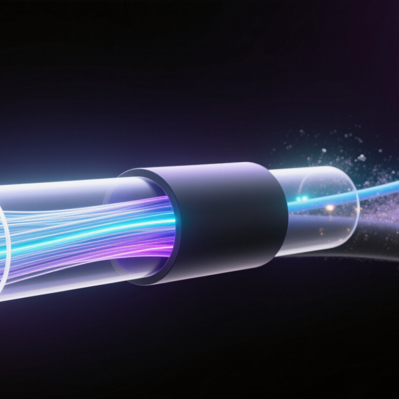
At the center of a fiber is a core, surrounded by glass called cladding. The core bends light inward because it has a higher refractive index. This effect, known as total internal reflection, keeps light guided along the strand. A transmitter converts electrical data into light pulses, often using a laser or LED. At the receiving end, a detector turns those pulses back into electrical signals. The pulses represent data. Their pattern carries the message.
That explanation is useful, but it leaves out details. Fiber type, wavelength, connectors, and equipment all affect performance. A dusty connector or a bend tighter than the manufacturer allows can weaken a signal. Installers therefore inspect connections and follow specified bend limits. For household broadband, the fiber may reach a building, while other cables connect individual rooms. The exact setup varies.
Optical fiber can offer high bandwidth and low signal loss compared with many copper links. It is also resistant to electromagnetic interference. Still, it is not automatically faster in every installation; network equipment and service plans matter too. A fiber cable is not simply a brighter replacement for copper. Understanding how light is guided helps explain both its strengths and its practical limits.
Optical Fiber: Definition, Structure, and Main Types
Optical fiber is a thin strand that carries data as pulses of light. A typical fiber has three basic layers: the core, cladding, and protective coating. The core guides light, while the cladding keeps it inside through total internal reflection. The outer coating protects the glass from moisture, scratches, and small bends.
Light carries the data. During installation, technicians must respect the cable’s bend radius. A sharp bend can increase signal loss, even when the cable looks undamaged. Clean connectors also matter. Dust on a connector can weaken the optical signal and create unstable performance. In practice, the structure is simple, but handling it requires care.
The main types are single-mode and multimode fiber. Single-mode fiber has a very small core and carries one light path. It supports long-distance communication with low signal dispersion. Multimode fiber uses a larger core and allows several light paths. It is commonly suited to shorter links inside buildings or facilities. The difference sounds straightforward, yet real networks can be less predictable. Cable length, connector quality, temperature, and installation skill all affect results. A careful design should match the fiber type to distance, bandwidth, and equipment. Otherwise, a technically correct cable may still deliver disappointing performance.
| Category | Dimension | Typical Data | Explanation |
|---|---|---|---|
| Definition | Basic description | Thin, flexible dielectric waveguide | Optical fiber transmits information as pulses of light through a glass or plastic medium rather than as electrical current through metal conductors. |
| Operating Principle | Light guidance | Total internal reflection | Light remains confined mainly within the core because the core has a higher refractive index than the surrounding cladding. |
| Structure | Core | Common glass-core diameters: about 8–10 µm for single-mode fiber and 50 or 62.5 µm for multimode fiber | The core is the central light-carrying region of the fiber. |
| Structure | Cladding | Typically 125 µm outside diameter for standard glass telecommunications fiber | The cladding surrounds the core and has a slightly lower refractive index to support light confinement. |
| Structure | Coating | Usually a polymer protective layer | The coating protects the glass from moisture, scratches, and small mechanical defects. It is not the primary optical guiding layer. |
| Cable Construction | Additional protection | Buffers, strength members, water-blocking materials, and an outer jacket | A finished fiber-optic cable may include several protective layers so it can withstand installation, pulling forces, bending, and environmental exposure. |
| Transmission | Signal conversion | Electrical signal → optical signal → electrical signal | A transmitter converts data into modulated light. A receiver detects the light and converts it back into an electrical signal. |
| Transmission | Common operating windows | Approximately 850 nm, 1310 nm, and 1550 nm | These wavelength regions are widely used because optical attenuation is relatively low and suitable light sources and detectors are available. |
| Main Type | Single-mode fiber | Core diameter commonly about 8–10 µm | Single-mode fiber carries one principal propagation mode and is generally used for long-distance, high-bandwidth communication. |
| Main Type | Multimode fiber | Core diameter commonly 50 or 62.5 µm | Multimode fiber carries multiple light paths and is commonly used for shorter-distance data communication and local networks. |
| Main Type | Step-index fiber | Uniform core refractive index with an abrupt change at the cladding boundary | This design has a sharp refractive-index transition between the core and cladding. It can be made in single-mode or multimode forms. |
| Main Type | Graded-index fiber | Core refractive index gradually decreases from the center outward | The gradual index profile helps reduce modal dispersion in multimode fiber by allowing different light paths to arrive more closely together. |
| Performance | Attenuation | Often specified in dB/km; lower values indicate less signal loss | Attenuation is caused mainly by absorption, Rayleigh scattering, connector loss, splice loss, and bending. |
| Performance | Dispersion | Modal, chromatic, and polarization-mode dispersion | Dispersion spreads an optical pulse over time and can limit the distance or data rate of a link. |
| Performance | Bandwidth | Determined by fiber type, wavelength, equipment, and link design | Fiber can support very high data rates, but the practical capacity of a system depends on the complete transmission path and active equipment. |
| Advantages | Electromagnetic immunity | Unaffected by electromagnetic interference during normal operation | Because the signal is carried as light in a dielectric material, optical fiber does not pick up electromagnetic interference in the same way as metallic cabling. |
| Advantages | Electrical isolation | No conductive electrical path between endpoints | Fiber can help prevent ground loops and is suitable for environments where electrical isolation is important. |
| Advantages | Size and weight | Small diameter and low weight compared with many copper cables of similar capacity | High information capacity can be carried through relatively lightweight cables, which is useful in dense communication systems. |
| Limitations | Mechanical sensitivity | Excessive pulling, crushing, or bending can cause loss or breakage | Glass fiber requires appropriate handling, bend-radius control, cable protection, and properly prepared terminations. |
| Applications | Typical uses | Telecommunications, data centers, access networks, cable television, sensing, and industrial links | Optical fiber is used wherever high bandwidth, long reach, low signal loss, or resistance to electromagnetic interference is required. |