What Is a Special Hydraulic Cylinder?
A Special Hydraulic Cylinder is not simply a larger version of a standard actuator. It is engineered for unusual loads, limited installation space, extreme temperatures, corrosive environments, or demanding motion control. Its design may include stainless-steel components, ceramic coatings, integrated position sensors, locking mechanisms, or custom sealing systems. Small details matter. A damaged rod seal can stop a steel press, offshore winch, or mobile crane.
Market data shows why this specialization matters. Grand View Research reported that the global hydraulic cylinders market reached approximately USD 14.6 billion in 2023. It also forecasts steady growth through 2030, supported by construction, agriculture, mining, and industrial automation. MarketsandMarkets identifies customization, electrification, and intelligent condition monitoring as important industry trends. These reports describe market direction, not guaranteed performance. That distinction deserves attention.
Hydraulic systems expert Anthony Esposito summarizes the operating principle clearly: “Hydraulics transmits power through a confined liquid.” A Special Hydraulic Cylinder extends that principle through tailored materials, geometry, and control features. Engineers commonly reference ISO 6020/2 and ISO 6022 when specifying mounting dimensions and operating conditions. However, compliance alone does not prove suitability. A cylinder may meet a standard and still fail under side loading, poor alignment, contaminated oil, or repeated shock.
The practical question is not, “How powerful is it?” It is, “What must it survive?” That answer should include force, stroke, speed, pressure, duty cycle, temperature, corrosion exposure, and maintenance access. Even experienced teams can underestimate installation realities. A careful specification, documented testing, and traceable manufacturing records provide stronger confidence than impressive catalog numbers.
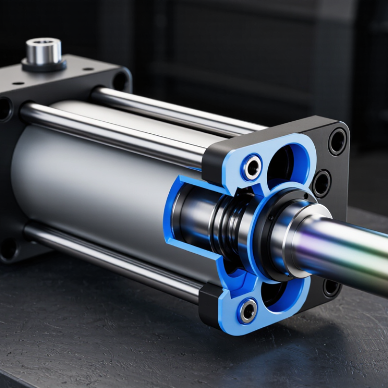
What Defines a Special Hydraulic Cylinder Beyond Standard Designs?
What Is a Special Hydraulic Cylinder?
A special hydraulic cylinder is defined by its application, not simply by unusual size. It solves constraints that standard designs cannot handle reliably. These constraints may include limited installation space, side loading, extreme temperatures, corrosive surroundings, synchronized movement, or strict stroke accuracy.
Standard cylinders often use familiar bores, rods, seals, and mounting patterns. Special designs may require stainless materials, ceramic coatings, custom ports, position sensors, locking mechanisms, or integrated cushioning. ISO 4413 emphasizes risk control, cleanliness, and pressure management in hydraulic systems. The IEA’s Energy Efficiency 2023 report states that industry used about 37% of global final energy in 2022. Therefore, reducing leakage, friction, and unnecessary pressure is not a minor design detail. An oversized cylinder may deliver force, but it can also increase energy demand and slow response. That trade-off deserves a calculation, not a guess.
Tips: Define the load, stroke, speed, duty cycle, temperature, and mounting forces before selecting components. Request pressure-test records, seal specifications, material certificates, and fatigue assumptions. Check side-load limits carefully. Many failures begin with misalignment, not weak steel. A practical inspection should examine rod scoring, seal wear, oil contamination, and mounting looseness. The imperfect part is unavoidable: real machines rarely match the original drawings. Leave adjustment capacity where the application may change.
What Is a Special Hydraulic Cylinder?
A special hydraulic cylinder goes beyond a conventional single-stage design by using features such as multiple stages, unusual stroke-to-length ratios, custom mounting, position sensing, corrosion-resistant materials, or operation in demanding environments.
The chart shows the typical number of extending stages. Conventional cylinders generally use one stage, while telescopic cylinders use two or more nested stages to achieve a long stroke within a shorter retracted length. Stage counts above five are possible but are less common and highly application-specific.
How Bore, Rod Diameter, and Pressure Determine Cylinder Force
A special hydraulic cylinder is designed for a demanding application, not simply given a larger body.
Its useful force depends mainly on bore diameter, rod diameter, and working pressure. The bore controls piston area. A larger bore creates more force at the same pressure. Rod diameter matters during retraction because it reduces the active piston area.
The calculation is direct: force equals pressure multiplied by area.
For example, an 80 mm bore at 160 bar can produce about 80 kN during extension. With a 40 mm rod, retraction force falls to roughly 60 kN. The difference is significant. Engineers must also allow for seal friction, pressure loss, temperature changes, and mounting misalignment.
Real machines disagree.
In field design, I verify these figures against the actual load cycle, not just a catalog formula. A cylinder lifting a 4,000 kg load may need additional capacity during startup, when static friction is highest. The rated pressure must exceed normal working pressure without encouraging unsafe overloading.
Stroke length, rod buckling, side loads, and connection strength also deserve inspection. My first estimates often look too generous. A practical test under controlled conditions can reveal slower movement, heat buildup, or unexpected pressure spikes.
Special cylinders may use unusual dimensions, reinforced rods, corrosion-resistant materials, or position feedback, but their force still begins with bore, rod diameter, and pressure.
ISO 6020/2 Cylinders: 160 Bar Ratings and Dimensional Standards
What Is a Special Hydraulic Cylinder?
A special hydraulic cylinder is designed for a duty that standard models cannot safely or efficiently handle. Its bore, rod, mounting, stroke, sealing system, or materials may require adjustment. In many industrial applications, ISO 6020/2 cylinders provide a practical dimensional framework. The standard specifies a 160 bar nominal pressure rating and common mounting dimensions. This helps engineers compare replacement units and reduce installation changes.
ISO 6020-2:2015 defines key dimensions, including bore sizes, rod diameters, mounting interfaces, and allowable construction details. However, a 160 bar rating is not permission to exceed every operating limit. Temperature, side loading, fluid cleanliness, and cycling frequency can reduce service life. The ISO standard is useful, but it does not replace application testing. That part is often underestimated.
Tips: Confirm the working pressure, not only the rated pressure. Check rod buckling for long strokes. Measure the mounting points before ordering. Keep at least a small design margin. A 2023 fluid-power industry analysis from the National Fluid Power Association reported continued demand for efficient hydraulic systems, especially in mobile and industrial equipment. Yet efficiency depends on more than the cylinder. Poor alignment can create uneven seal wear, leakage, and premature failure. In practice, a carefully specified ISO 6020/2 cylinder may outperform a cheaper custom substitute, but the result still depends on installation quality and maintenance records.
Sources: ISO 6020-2:2015; National Fluid Power Association, 2023 industry data.
What Is a Special Hydraulic Cylinder? - ISO 6020/2 Cylinders: 160 Bar Ratings and Dimensional Standards
| Data Dimension | ISO 6020/2 Reference or Value | Technical Meaning |
| Cylinder series | ISO 6020/2 | A metric, compact hydraulic-cylinder series with standardized mounting dimensions for interchangeable design applications. |
| Nominal pressure | 160 bar (16 MPa) | The reference working-pressure rating of the series. Actual allowable pressure depends on construction, seals, temperature, duty cycle, and the certified product design. |
| Pressure equivalent | Approximately 2,320 psi | Conversion of 160 bar using 1 bar ≈ 14.5038 psi. The metric value remains the primary ISO reference. |
| Standardized dimensions | Mounting and envelope dimensions | The standard defines key interface dimensions used for installation and replacement. Exact dimensions must be taken from the applicable ISO dimensional tables and cylinder drawing. |
| Typical nominal bore sizes | 25, 32, 40, 50, 63, 80, 100, 125, 160, and 200 mm | These metric bore sizes are commonly used for ISO 6020/2-compatible cylinder designs. Availability and exact construction may vary by design specification. |
| Cylinder configuration | Usually selected as a single-rod or application-specific configuration | Rod diameter, stroke, cushioning, ports, seals, and mounting style must be specified separately for the intended machine. |
| Theoretical extension force formula | F = p × π × D² ÷ 4 | F is force in newtons, p is pressure in N/mm², and D is bore diameter in millimetres. The calculation excludes friction, pressure losses, and mechanical efficiency. |
| Return-force calculation | Fᵣ = p × π × (D² − d²) ÷ 4 | The retraction force is lower than extension force because the rod area is subtracted. D is bore diameter and d is rod diameter. |
| Bore diameter | 25 mm | Theoretical extension force at 160 bar: approximately 7.85 kN. |
| Bore diameter | 40 mm | Theoretical extension force at 160 bar: approximately 20.11 kN. |
| Bore diameter | 50 mm | Theoretical extension force at 160 bar: approximately 31.42 kN. |
| Bore diameter | 63 mm | Theoretical extension force at 160 bar: approximately 49.88 kN. |
| Bore diameter | 80 mm | Theoretical extension force at 160 bar: approximately 80.42 kN. |
| Bore diameter | 100 mm | Theoretical extension force at 160 bar: approximately 125.66 kN. |
| Bore diameter | 125 mm | Theoretical extension force at 160 bar: approximately 196.35 kN. |
| Bore diameter | 160 mm | Theoretical extension force at 160 bar: approximately 321.70 kN. |
| Bore diameter | 200 mm | Theoretical extension force at 160 bar: approximately 502.65 kN. |
| Stroke length | Application-specific | Stroke is selected according to the required travel. Long-stroke designs require checks for rod buckling, side loading, alignment, and speed. |
| Cushioning | Optional, application-dependent | Adjustable or fixed cushioning can reduce end-of-stroke impact, especially at high speed or with heavy moving loads. |
| Important selection note | Verify the complete technical drawing | ISO compatibility does not make every cylinder dimension interchangeable. Confirm bore, rod diameter, stroke, mounting type, port geometry, envelope dimensions, sealing system, and operating conditions before installation. |
ISO 6022 Cylinders: 250 Bar Ratings for Heavy-Duty Applications
What Is a Special Hydraulic Cylinder?
ISO 6022 Cylinders: 250 Bar Ratings for Heavy-Duty Applications
A special hydraulic cylinder is designed for demanding motion, force, or installation conditions. ISO 6022 cylinders belong to a standardized 250 bar series for heavy-duty hydraulic systems. Their defined mounting dimensions help engineers replace or integrate cylinders more reliably. The standard supports consistent design decisions across presses, steel equipment, material handling systems, and industrial machinery.
A 250 bar rating indicates substantial pressure capacity, but it is not a complete safety guarantee. Actual performance depends on rod size, piston diameter, seals, temperature, side loading, and hydraulic fluid quality. A cylinder may reach its rated pressure briefly, yet continuous operation can require a lower working limit. Engineers should confirm the duty cycle, peak pressure, and return-line conditions before selection.
In field inspections, uneven rod wear often reveals poor alignment rather than weak cylinder construction. That detail is easy to miss. Mounting surfaces must remain rigid and accurately aligned. The rod should not carry unintended bending loads. Contamination can also damage seals quickly, especially in dusty or wet environments. I have found that pressure calculations are often careful, while installation checks receive less attention. That imbalance deserves correction. A reliable ISO 6022 application combines standard dimensions with verified materials, suitable seals, controlled maintenance, and documented pressure testing.
Special Cylinder Types, Materials, Sensors, and Custom Applications
A special hydraulic cylinder is engineered for a duty that standard cylinders cannot handle reliably. It may use a telescopic, tandem, welded, or mill-duty design. Each type solves a different problem. Telescopic cylinders fit limited spaces, while tandem cylinders deliver force through staged piston areas.
Material selection changes service life. A hardened, chrome-plated rod resists scoring and corrosion. Stainless steel suits washdown areas, although it can increase cost. High-strength alloy steel supports heavy loads and repeated shock. Seals also matter. A cylinder working near 80°C needs compounds rated for heat, pressure, and fluid compatibility.
The 2024 MarketsandMarkets report estimated the global hydraulic cylinder market at about USD 14.3 billion in 2022. It projected growth to roughly USD 19.4 billion by 2027. That expansion reflects more demand for automation and condition monitoring. Sensors now include magnetostrictive position sensors, LVDT systems, proximity switches, and pressure transducers. They can report stroke position within fractions of a millimeter. Useful, but not always necessary.
I have seen custom cylinders designed for refuse compactors, steel mills, mobile cranes, and injection equipment. Engineers may specify unusual mounting, side ports, hollow rods, or integrated valves. The ISO 6020/2 and ISO 6022 standards help define dimensional and performance expectations. Still, field conditions can expose gaps. A sensor may fail from vibration, while a perfect seal may degrade under contaminated oil. Good customization begins with measured loads, cycle counts, temperature, oil quality, and maintenance access—not guesswork.
