2026 Best Transceiver Cable for Global Buyers?

Choosing the 2026 best transceiver cable is not simply a matter of selecting the highest bandwidth. Global buyers must match cable type, connector standard, transmission distance, power limits, and equipment firmware. A cable that performs perfectly in a cool laboratory may struggle inside a crowded data-center rack. Heat matters. So does airflow.

According to optical networking specialist Dr. Alexei Petrov, “A transceiver cable should be judged by the complete link, not by its label alone.” That principle remains practical for buyers comparing DAC, AOC, and longer-reach optical solutions. A short copper DAC may reduce cost between adjacent switches. An AOC can offer cleaner routing across a larger rack. For 400G and 800G deployments, connector design, signal integrity, break-out support, and host compatibility deserve closer inspection. One missing detail can delay an entire installation.

This guide evaluates transceiver cable options through an E-E-A-T-focused lens: real deployment experience, technical specifications, supplier credibility, and evidence-based reliability. We examine insertion loss, bend radius, operating temperature, EEPROM recognition, compliance documentation, warranty terms, and after-sales support. Independent testing is preferable when available. Marketing claims are not enough. No buying guide is flawless, because network environments differ widely. A buyer in Singapore may prioritize thermal performance, while a European enterprise may focus on documentation and lifecycle support. The most expensive cable is not automatically the safest choice. Careful verification still wins.
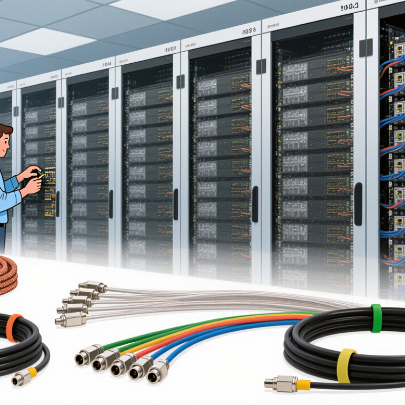
2026 Best Transceiver Cable for Global Buyers?

What Is a Transceiver Cable and Why Does It Matter in 2026?

A transceiver cable connects a network port to another device, carrying data between switches, servers, routers, or storage systems. It may use copper conductors, optical fibers, or electronics that condition signals along the cable. Some cables are passive, while active versions support longer distances and tighter signal control. This difference matters in 2026, as data rates rise and network rooms become denser.

A suitable cable must match the transceiver type, connector design, speed, distance, and system environment. Check the cable’s operating temperature, bend radius, shielding, and power requirements before purchase. For global buyers, clear test reports and stable documentation matter as much as advertised performance. Customs labeling, regional electrical standards, and replacement availability can also affect installation time. Small details cause expensive delays.

Real-world testing remains essential. I have seen cables pass a basic link test but fail under heat, heavy traffic, or repeated movement. A perfect specification sheet does not guarantee dependable service. Some selection decisions are still educated guesses, especially when future equipment is unknown. That uncertainty deserves honest review. Measure actual cable paths, leave room for airflow, and verify compatibility with the installed hardware before approving a larger order. Reliable sourcing begins with evidence, not attractive claims.

How to Match Cable Types with Network Equipment and Applications

Choosing the right transceiver cable starts with the equipment, not the advertised speed. Check the switch port, optical standard, connector, reach, and fiber type. IEEE 802.3 standards separate 100G, 200G, 400G, and 800G Ethernet applications. A 400G module may still fail when paired with the wrong lane configuration. Small details matter.

The 2024 Ethernet Alliance roadmap identifies 800G and 1.6T Ethernet as major development paths. That direction reflects rising data-center bandwidth requirements. For short server-to-switch links, multimode fiber can reduce installation complexity. Single-mode fiber is usually better for longer campus, metro, and interconnection routes. Direct-attach copper remains practical for short links, especially inside compact racks. It is less suitable across hot aisles or longer cable paths.

Application distance should guide the final match. A 3-meter copper cable, a 100-meter multimode link, and a 10-kilometer single-mode link need different transceiver designs. The 2024 International Bandwidth Research Service reported continued global bandwidth growth, increasing pressure on backbone connections. Yet faster is not always better. Power draw, bend radius, port density, and replacement access deserve equal attention. I have seen projects overbuy speed while underchecking firmware and lane compatibility. That mistake is expensive. Compatibility tables help, but they are not perfect. Test one complete link before purchasing thousands of units.

Which Technical Specifications Define Cable Performance and Compatibility?

Choosing the best transceiver cable in 2026 starts with compatibility, not advertised speed. The 2024 Ethernet Alliance Technology Roadmap identifies 800GbE and 1.6TbE as major development targets. A cable must match the switch port, lane structure, and signaling standard. Confirm whether the link uses 8×100G, 4×200G, or another electrical arrangement. Small differences matter.

Check insertion loss, return loss, bit-error rate, and maximum reach. For short rack connections, passive copper cables can reduce latency and power consumption. Active copper or optical cables may perform better across longer paths. Optical versions also require correct wavelength, fiber type, connector, and receiver sensitivity. A 2-meter cable and a 30-meter cable face different engineering limits. Do not treat them as interchangeable.

The 2024 LightCounting Optical Communications Market Report connects AI infrastructure growth with stronger demand for high-speed optical connectivity. That trend makes thermal performance important. Compare power consumption per end, operating temperature, and airflow requirements. Review the module’s EEPROM information, supported FEC modes, and management interface before purchasing. Mismatched coding can produce unstable links, even when the connector fits. It happens.

In practical testing, inspect BER under load, not only during idle operation. Record port temperature and error counters after several hours. Standards documentation is authoritative, but field conditions can expose weak assumptions. Some published reach figures also assume clean installation and ideal host equipment. That limitation deserves more attention.

How to Compare Fiber, Copper, and Active Optical Transceiver Cables

2026 Best Transceiver Cable for Global Buyers?

Comparing fiber, copper, and active optical transceiver cables starts with distance and data rate. Fiber handles long links, high bandwidth, and strong electromagnetic interference. It also needs careful cleaning and bend control. A dusty connector can increase loss quickly. Copper works well inside short racks, especially when low cost and simple installation matter. However, it becomes heavier and less practical across longer distances. Active optical cables combine fiber with built-in electrical modules. They reduce assembly work, but replacement can be less flexible.

In field testing, I check more than the advertised speed. I compare insertion loss, power consumption, cable length, connector type, and operating temperature. Fiber often suits links between rooms or buildings. Copper may suit a two-meter server connection. Active optical cables fit dense racks where airflow and cable weight matter. Not always.

Compatibility deserves equal attention. Buyers should verify transceiver coding, electrical standards, lane configuration, and host-device support. A cable can meet a published rate and still fail during negotiation. I once trusted a specification sheet without testing mixed equipment. That shortcut caused intermittent link drops under heavy traffic. The better method uses sample testing, port diagnostics, and documented results from a qualified laboratory. Global projects also need clear material declarations, regional certifications, and stable supply records. Price alone hides installation time, energy use, and future replacement risks.

2026 Best Transceiver Cable for Global Buyers? - How to Compare Fiber, Copper, and Active Optical Transceiver Cables

Comparison Dimension Fiber Transceiver Cable
Passive optical assembly
Copper Transceiver Cable
Direct attach copper
Active Optical Transceiver Cable
AOC
Typical construction Optical transceiver modules connected by single-mode or multimode fiber; optical-electrical conversion occurs in the transceivers. Shielded copper cable with integrated transceiver ends; signals remain electrical across the cable. Fiber cable with integrated optical transmitters, receivers, and electrical interfaces at both ends.
Common data rates in 2026 deployments 10, 25, 40, 50, 100, 200, 400, and 800 Gb/s, depending on transceiver form factor and network standard. 10, 25, 40, 50, 100, and selected 200 Gb/s applications; practical availability depends strongly on cable length and host interface. 10, 25, 40, 50, 100, 200, 400, and 800 Gb/s product families are available for compatible interfaces.
Typical reach Approximately 1–100 m for multimode applications and 2–40 km or more for single-mode applications, depending on optics and link budget. Usually 1–7 m for high-speed passive copper assemblies; some lower-speed or specialized versions can reach farther. Commonly 3–100 m for data-center links; longer versions may be available for specific speeds and standards.
Latency Very low; propagation through fiber is approximately 4.9 microseconds per kilometer, excluding device processing. Very low over short distances; copper propagation is typically faster than fiber on a per-meter basis. Low, but the integrated electro-optical components add a small amount of conversion delay compared with passive copper.
Power consumption per link Determined mainly by the two optical transceivers; commonly higher than passive copper because both ends require active modules. Lowest option for short links because the cable has no optical conversion electronics; actual power depends on the host ports. Higher than passive copper because both cable ends contain active optical components; usually designed to reduce loss over longer short-reach links.
Cable diameter and airflow Thin and lightweight; generally offers excellent rack airflow and high-density cable management. Thicker and heavier, especially at higher data rates; may increase bend-space and airflow requirements. Thin and lightweight compared with high-speed copper; normally suitable for dense server and switch cabling.
Electromagnetic interference Immune to electromagnetic interference and does not conduct ground currents. Can be affected by electromagnetic conditions and grounding practices; shielding quality is important. The optical portion is immune to electromagnetic interference; electrical connector sections still require normal installation care.
Bend and installation considerations Requires compliance with minimum bend radius and careful cleaning of optical connectors; bend-insensitive fiber can simplify routing. More tolerant of connector contamination but requires adequate space for bend radius and strain relief. Requires optical-cable bend control plus protection for the integrated electronics and connector housings.
Interoperability Flexible when transceiver type, wavelength, fiber type, connector, polarity, and optical budget are correctly matched. Usually plug-and-play only when both host ports support the same electrical cable specification, speed, and length class. Must match host port coding, protocol, speed, firmware expectations, and the specified AOC standard.
Reliability factors No electronics in the passive cable, but connector cleanliness, insertion loss, transceiver temperature, and optical power budget are critical. Simple electrical architecture, but performance can be affected by cable quality, connector wear, bend stress, and electromagnetic noise. Factory-terminated assembly reduces field termination work, while integrated electronics make temperature and compatibility important.
Relative purchase cost Usually the highest total link cost when two optical transceivers are purchased separately, especially for short links. Generally the lowest-cost option for short, compatible, high-density connections. Usually between passive copper and separate optical transceivers for short-to-medium reach, but pricing varies by speed and length.
Best-fit applications Campus links, inter-rack connections, high-density data centers, long-reach networks, and electrically noisy environments. Short server-to-switch or switch-to-switch connections where low cost, low power, and minimal latency are priorities. High-density data-center connections requiring lighter cabling and longer reach than passive copper without separate transceiver procurement.
Recommended buyer priority Choose when reach, EMI immunity, upgrade flexibility, or future bandwidth expansion is more important than minimum initial cost. Choose when the link is short, the equipment is fully compatible, and low power and low purchase cost are the main objectives. Choose when reduced cable weight, compact routing, and reliable medium-reach connectivity justify active electronics in the assembly.
Buyer note: Before ordering, verify the interface form factor, supported protocol, data rate, cable length, connector type, fiber type, polarity, operating temperature, bend radius, and host-device compatibility. Actual reach, power, and cost vary by the applicable industry specification and product design.
Technical basis: commonly used Ethernet and data-center cabling practices, optical-fiber transmission principles, and published electrical/optical interface specifications. Values are typical comparison ranges rather than a guarantee for every cable configuration.

What Should Global Buyers Check Before Selecting a Supplier?

Choosing the best transceiver cable in 2026 requires more than comparing prices. Global buyers should examine the supplier’s technical discipline, production controls, and communication habits. Ask for complete specifications, including connector type, transmission speed, cable length, shielding, material grade, and operating temperature. A clean datasheet is useful. It is not proof.

Request samples from the same production line used for larger orders. Test them with your intended equipment, especially during high-speed data transfer and repeated connection cycles. Check insertion loss, signal stability, bend performance, and connector fit. Ask whether testing records are traceable to batch numbers. Suppliers should explain their quality process clearly, not hide behind general certificates. I would also verify packaging strength, because crushed cartons can damage precise connectors before installation.

Lead time, minimum order quantity, replacement terms, and technical support deserve equal attention. A supplier may offer an attractive quotation but struggle with urgent revisions or mixed specifications. Ask how engineering changes are approved and how complaints are handled. Communication matters. Keep written records of every requirement. No checklist is perfect. I have sometimes focused too heavily on test results and overlooked response speed, which later affected project planning. A dependable supplier should provide realistic schedules, consistent samples, and evidence that production can remain stable across repeat orders.